Biomechanical Hoof Tester
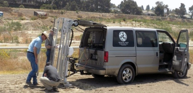
The Orono Biomechanical Hoof Tester is a system that has been developed to make it possible to load the track at the rate and loads that are applied by a horse at a gallop (Peterson et al. 2008). This system mimics the point at which the fore limb contacts the track and the weight of the horse is transferred to the hoof. This is the period of the gait during which both the highest vertical loads and the highest shear loads are applied to the soil. The device that has been  developed is a two axis drop tower type of apparatus which impacts a synthetic hoof at an angle to the soil surface. Two non-orthogonal axes of motion allow acceleration due to the sliding of the hoof in contact to be measured as well as vertical loads and vertical acceleration. From Figure 3 the two axes can be seen as a long set of rails and a shorter linear bearing apparatus which is attached to the hoof. With gravity acting on the first axis, the long rails on which the hoof and instrumentation slides, the force is generated by accelerating this mass down the rails. The total mass of the portion of the system that drops on the long rails is 30 kg which provides energy at impact of approximately 540 J. This impact energy accounts for the energy of the hoof impacting the surface as well as the partial weight of the animal and associated musculature. A second set of shorter linear rails moves down as a part of the mass attached to the slide.
  This second axis is preloaded by a gas spring and only moves once the hoof is in contact with the soil. The difference in the angle between the first and second axes, 5 degrees from the long rail angle, forces the hoof to slide forward towards the toe as it impacts the soil and the second preloaded axis is compressed. The angle at which the hoof impacts the soil is adjusted to match the published biomechanical data for initial impact of the hoof. A total of five data channels are recorded during the testing. Attached to a stiff mass above the hoof is a three axis 100 g accelerometer. Load is transferred into the gas spring from the hoof mass using a dynamic load cell with a 0 Hz (DC) to 36 kHz bandwidth. Redundant data from the acceleration and the position measurement is used to estimate the penetration into the soil and to verify the velocity of the hoof at impact. The angle of the hoof with respect to the soil is adjusted to 7 degrees from the vertical to match treadmill data from horses at a gallop. Some data is currently available from the Biomechanical Hoof Tester; however it remains to be shown that the dynamic response is correlated with the response of the horse at a gallop.
The biomechanical hoof tester replicates the speed and impact of one of the most critical phases of the gait for risk to the horse. While the two measured characteristics, shear and impact force, are expected to be related to performance of the horse, it is even more likely that these parameters measured with the full load and speed of the hoof landing represent the risk to the horse of catastrophic injury to the forelimb. The system has also been adapated to match the biomechanics of the leading forelimb of a horse landing during a show jumping event (Hernlund et. al., 2013). Two systems are now in use in the United States, one in the United Kingdom and another machine based in Sweden.
Peterson, M.L., McIlwraith, C.W., and Reiser, R.F. (2008) “Development of a system for the in-situ characterization of thoroughbred horse racing track surfaces.” Biosystems Engineering 101: 260-269.
Elin Hernlund, Agneta Egenvall, Michael L. Peterson, Christie A. Mahaffey, Lars Roepstorff, “Hoof accelerations at hoof-surface impact for stride types and functional limb types relevant to show jumping horses", The Veterinary Journal, Vol. 198, Suppl 1, December 2013, Pages e27–e32
California Horse Racing Board (CHRB) OBST Info
- Labview Screenshot with Wiring Diagram (pdf)
- Labview Source Code (.zip)
- Operating Manual (.pdf)
- Vended Parts List (.xlsx)
- Bill of Materials (.xlsx)
- Drawing Package (.pdf)
- SolidWorks Drawing Package (.zip)
- Calibration Fixture (.stp)
© 2015 Biologically Applied Engineering